
 English
 中文简体
中文简体 русский
 Español
The conveyor sealing plate is a side enclosure component designed for conveyor e...

Industry News
Home / News / Industry News / Conveyor Turning Machine Components: Selection Guide for Durable Curve Transfer
Conveyor Turning Machine Components: Selection Guide for Durable Curve Transfer
Author: admin / 2026-09-09
Content
- 1 Why Curve Sections Fail Before the Rest of the Line
- 2 The Core Component Set of a Turning Machine
- 3 Mecanum Wheels for Continuous Directional Control
- 4 Top Lifting Transfer Wheels for Intermittent Direction Changes
- 5 Supporting Parts: Sleeves, Bases, Guardrails, and Flow Bars
- 6 Material and Tolerance Considerations
- 7 A Practical Selection Checklist
When a distribution center added a new 90-degree curve to its sortation line, the first prototype failed within three days. Parcels piled up at the inner edge, the drive chain jumped, and the roller sleeves showed visible scoring. The cause was not the conveyor frame but the conveyor turning machine components.
A conveyor turning machine—also called a curve conveyor, a turning conveyor, or a transfer turn—is the section of a line that changes the direction of moving goods. On a straight line, rollers and belts share the load evenly. On a turn, the inner and outer edges cover different distances in the same time, creating a speed differential, side thrust, and concentrated wear. The practical result is simple: a curve section is only as reliable as the components used to build it. Selecting the right components is not a secondary detail; it is the main design decision.
Why Curve Sections Fail Before the Rest of the Line
When a conveyor system shuts down unexpectedly, the turning section is often the first place to look. Product jams tend to happen at the transition from straight to curved travel because the goods need to rotate while continuing forward. If the carrying surface does not allow that rotation, the carton or tote skids, tilts, or stops.
Another common failure is uneven wear on the drive train. A driven roller curve requires different peripheral speeds across its width. If standard straight rollers and chain wheels are used instead of tapered or specially angled parts, the rollers fight each other. The result is premature bearing wear, stretched drive chains, and accumulating noise.
Material handling operations in logistics, food and beverage, pharmaceutical, warehousing, tire manufacturing, and airport ground service all face the same constraint. Turning machines must handle package sizes and weights that vary by shift, and they must do it with low maintenance. That is why the decision starts with components, not with the steel frame.
The Core Component Set of a Turning Machine
A curved conveyor is not a single product; it is an assembly of standard and specialized parts. The table below summarizes the components that determine turning behavior.
| Component | Function on a Turn | Typical Plastic Materials |
|---|---|---|
| Mecanum wheel | Generates lateral motion for omnidirectional direction control | PP body, PU roller surface |
| Top lifting transfer wheel | Lifts the load and shifts it sideways at a transfer point | POM or PA wheel, steel core |
| Tapered roller sleeve | Compensates for the speed difference between inner and outer radii | UHMWPE, PP |
| Retainer ring and plastic seat | Lock the roller and sleeve in position against axial movement | PP with glass fiber |
| Chain wheel and pulley | Transmits torque to the driven rollers on a power curve | POM, PA |
| Guardrail and sealing plate | Keep the product on the curve and prevent debris from entering the drive | PP, PVC |
| Flow bar | Creates a low-friction slide for gravity or manual curves | UHMWPE |
The right combination depends on the turning method. A belt turn uses a conical belt and tapered pulleys; a roller turn uses tapered or individually driven rollers; a lift-and-transfer station uses intermittent lifting wheels. For each method, plastic components control friction, wear, and noise.
Mecanum Wheels for Continuous Directional Control
In a turning machine, mecanum wheels offer a compact way to control the direction of a load without a turntable or a complex roller curve. Each mecanum wheel has free-rolling rollers mounted at an angle around its circumference. By driving the wheels at different speeds and rotations, the load can move forward, backward, diagonally, or sideways. This makes mecanum wheels useful for short-radius turns, for centering products, and for sections where the conveyor direction must change without a large footprint.
The main advantage is continuous motion. The load never stops while its orientation is corrected, which keeps throughput high. Mecanum wheels are especially effective in AGV systems and automated transfer stations where the turning machine must be part of a floor-mounted vehicle rather than a fixed curve.
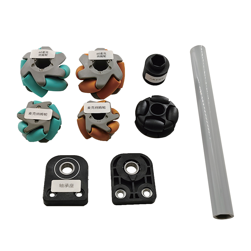 Omnidirectional Mecanum Wheel for Precise AGV MovementThis wheel's angled rollers enable zero-radius turns and lateral shifts without steering, making it ideal for floor-mounted transfer stations that must keep cartons moving continuously.View Product →
Top Lifting Transfer Wheels for Intermittent Direction Changes
When the turn is a discrete operation rather than a continuous curve, top lifting transfer wheels are the more common solution. These wheels sit below the conveyor bed and are raised when a carton reaches the transfer point. The load lifts off the line, the wheels rotate, and the product moves sideways onto a cross conveyor. Then the wheels lower and the main line continues.
Top lifting transfer wheels are used for 90-degree transfers in carton handling, tote systems, and palletless goods movement. They work well where space is limited and where the line must handle two different directions at the same elevation. Compared with a long curve, a lift-and-transfer station takes less floor space and provides a positive, repeatable change of direction.
Because they are raised and lowered repeatedly, these wheels must have stable dimensions and strong resistance to impact. A plastic wheel with a steel core offers the right balance of low mass and load capacity. The wheel surface also needs a controlled coefficient of friction: high enough to grip the carton during transfer, but low enough to avoid scuffing the bottom surface.
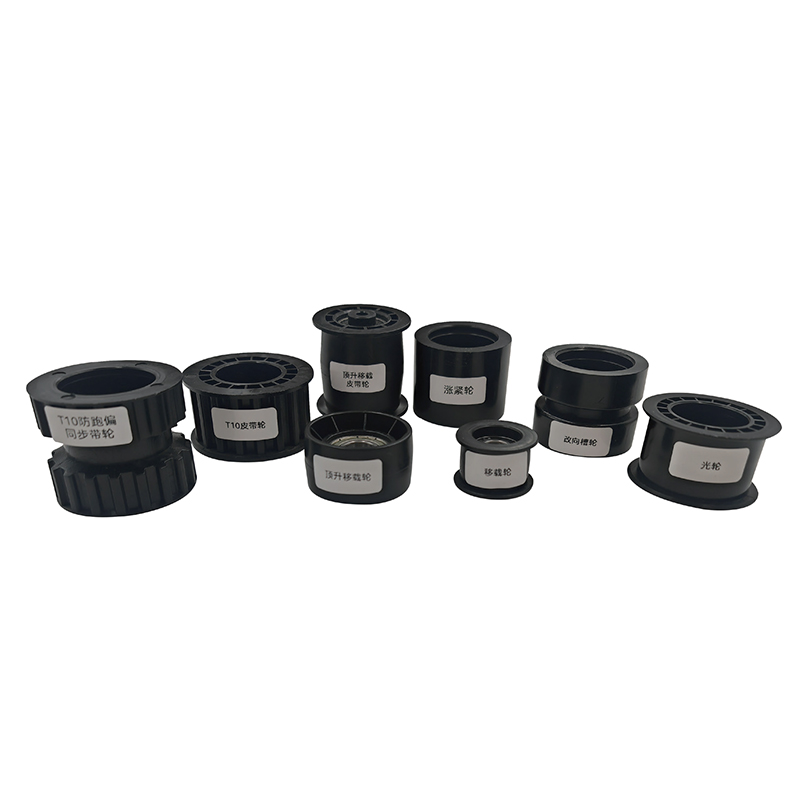 Top Lifting Transfer Wheel for Right-Angle Conveyor TransfersRaised and lowered beneath the line, this wheel lifts cartons off the bed and rotates them onto a cross conveyor. Its steel-core plastic body balances impact resistance with low mass.View Product →
Supporting Parts: Sleeves, Bases, Guardrails, and Flow Bars
Behind the headline components are the support parts that keep a turning machine running. In a roller-based curve, the roller sleeve is the contact surface that determines how gently the product moves through the bend. Tapered sleeves are used on true curve conveyors to match the speed difference across the width; straight sleeves with close tolerances are used on short transfers where a small gap is acceptable. A retainer ring locks the sleeve axially, and a plastic seat holds the roller assembly in place on the frame.
Guardrails are equally important. A curved section generates lateral force that pushes products toward the outer edge. A smooth guardrail with a low-friction profile reduces the risk of jams and protects fragile packaging. Sealing plates underneath the chain path stop dust and small debris from entering the drive components.
Gravity curves use a different approach. Instead of driven rollers, they rely on low-friction flow bars that let a box slide around the bend under its own weight. This is common for lightweight parcels and empty tote return lines. The bar surface must be abrasion resistant, and the edge profile must not catch on tape or labels.
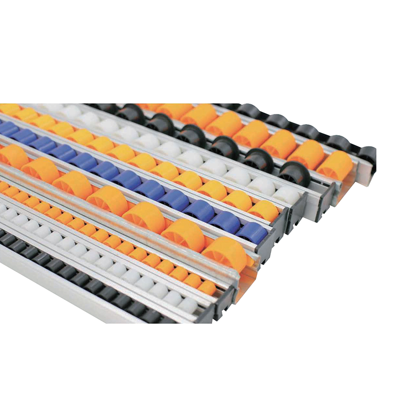 Low-Friction Conveyor Flow Bar for Gravity CurvesThis bar lets lightweight parcels and empty totes slide around bends under their own weight. Its abrasion-resistant surface and smooth edges keep labels and tape from snagging.View Product →
For a deeper look at how roller-related parts are matched to each other, refer to our conveyor roller fittings types and selection guide.
Material and Tolerance Considerations
Plastic is the dominant material in turning machine components because it offers low friction, corrosion resistance, and noise damping. The material choice changes the behavior of the part.
- UHMWPE has a very low coefficient of friction and good wear resistance, making it suitable for slide surfaces and sleeve liners.
- POM (acetal) is stiff and dimensionally stable, which suits precision parts like wheels, pulleys, and chain wheels.
- PP (polypropylene) is cost-effective and chemically resistant, but it is softer and often used for bases, guardrails, and housings.
- PA (polyamide) offers high impact strength, but it can absorb moisture and change dimensions in humid environments, so tolerance must be verified.
Tolerance matters more than many buyers expect. A sleeve or wheel that is 0.5 mm undersized will rattle and wear unevenly; one that is oversized can seize on the roller shaft. Before placing a large order, check the measured diameter, the bore concentricity, and the gap between parts. A qualified manufacturer will provide datasheets and samples for trial installation.
A Practical Selection Checklist
When specifying conveyor turning machine components, use the following list to avoid common procurement mistakes.
- Define the turn type: continuous roller curve, belt turn, gravity slide, or lift-and-transfer station.
- Measure the inner radius, outer radius, and conveyor width.
- Record product footprint, weight, and maximum throughput rate.
- Check the drive arrangement: shaft diameter, wheel bore, chain pitch, and mounting hole spacing.
- Confirm the operating environment: temperature, humidity, chemical exposure, and whether the line requires food-safe materials.
- Request samples to verify noise, fit, and finish before the full quantity is produced.
- Plan spare parts for the highest-wear items: sleeves, lifting wheels, and guide strips.
A turning machine built with the wrong components will fail slowly at first, then suddenly. The cost of replacing a worn wheel or broken base after installation is far higher than the cost of choosing the right conveyor turning machine components at the design stage.
Related products
-
-
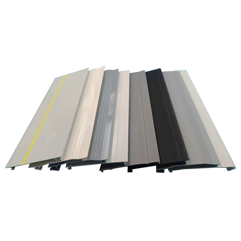
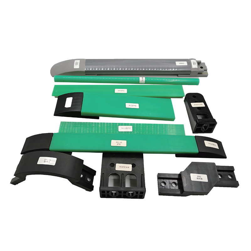 Conveyor Guardrail
The conveyor guardrail is a modular protective structure installed along the per...
-
 Conveyor Flow Bar
The conveyor flow bar is a rolling component designed for gravity-driven or assi...
-
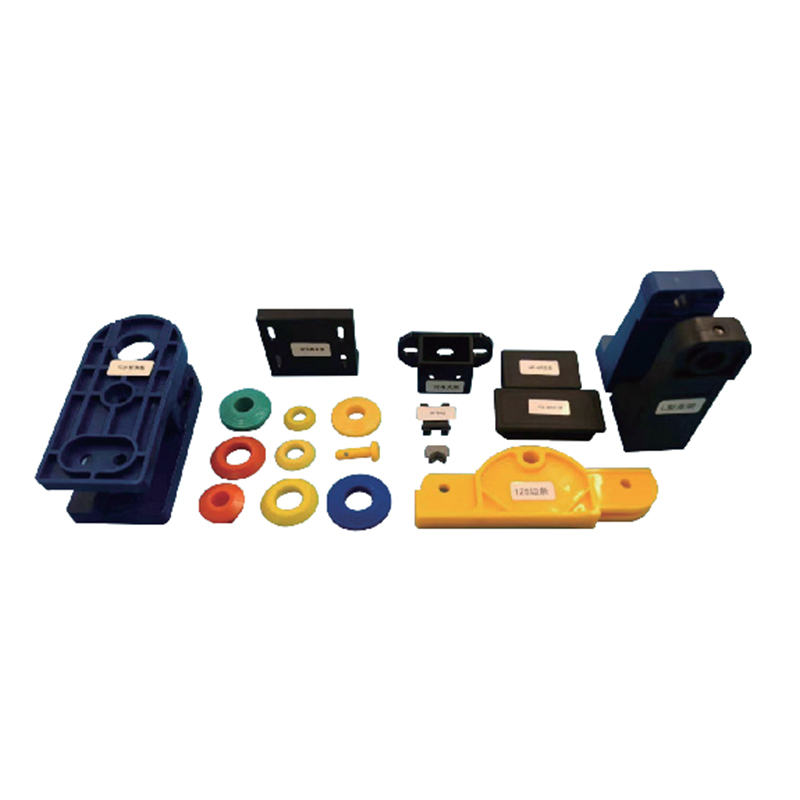 Conveyor Accessories
Conveyor accessories are a collection of functional components designed for indu...
-
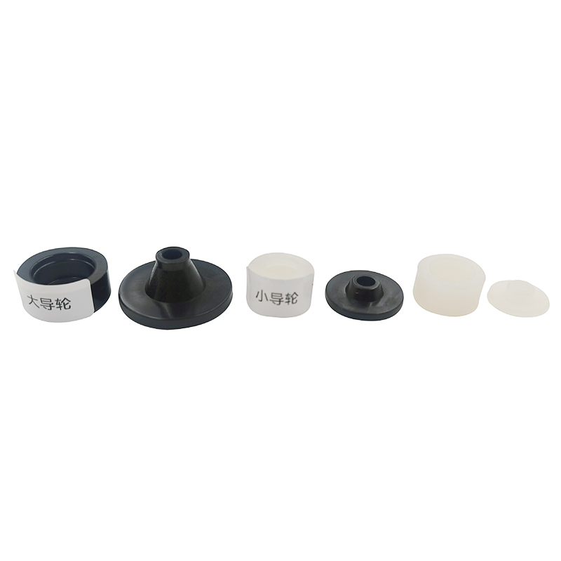 Roller Guide Wheel
The guide wheel serves as a critical directional component in industrial conveyi...
-
 Top Lifting Transfer Wheel
The TOP LIFTING TRANSFER WHEEL integrates lifting and transferring functions, ty...


+86-13250912999
Huzhou Nanxun Guan's Plastic Industry Co., Ltd.
Email: [email protected]
Address: Building 8, North Zone, Dehao Industrial Park, Linghu Town, Nanxun District, Huzhou City, Zhejiang Province, China
Navigation
Products
About us
Copyright © Huzhou Nanxun Guan's Plastic Industry Co., Ltd.
All Rights Reserved.
 Wholesale Plastic Conveyor Parts Manufacturers